Derivation of Thin Film Interference
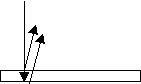 |
Consider light incident on a thin slab of glass
whose index is nag. The slab is
situated in vacuo.The wave equation yields
line 1 outside the glass |
|
1 |
 |
|
Inside the glass the wave equation yields line 2. |
2 |
 |
|
Divide line 1 by line 2 to get line 3. |
3 |
 |
|
The left hand side of line 3 is the definition of index
of refraction for glass. |
4 |
 |
|
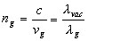
Line 5 shows that the wavelength of light is different
in glass than in vacuo. |
5 |
 |
|
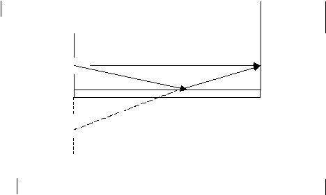
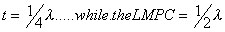
Two factors contribute to interference--path length
difference and the Lloyd's mirror effect. We get constructive
interference if the PLD is one half wavelength and the thickness
is 1/4 wavelength |
6 |
 |
|
constructive interference occurs for other thicknesses,
namely, odd multiples of quarter wavelengths. We generate these
values as shown |
7 |
 m = 0, 1, 2... m = 0, 1, 2... |
|
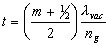
Line 7 shows the wavelength in glass. We need the wavelength
in vacuo. We substitute from line 5. |
8 |
 m = 0, 1, 2... m = 0, 1, 2... |
|
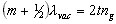
Rearranging terms, line 9 describes constructive
interference |
9 |
 m = 0, 1, 2... m = 0, 1, 2... |
|
Destructive interference
comes when the thickness is even multiples of quarter wavelengths |
10 |
 m = 0, 1, 2... m = 0, 1, 2... |
|
Finally, lines 9 & 10 work when the LMPC applies
to just one surface of the film. If the LMPC occurs at both surfaces,
then the equations at lines 9 & 10 are REVERSED |